Where, D is the distance between radar station and object in nautical miles. T is the total time from transmission of the signal and reception of the signal in micro-sec. In most of the radar applications, Nautical mile is used in place of statute miles for the measurement purposes. A Nautical mile is equal to 6076 ft.
Wednesday, June 26, 2019


Zigbee Network Overview:

As mentioned in the network diagram, zigbee network is comprised of coordinator(C), router(R) and end devices (E). Zigbee supports mesh-routing. For detailed information on routing protocol employed in zigbee, one may refer Ad-hoc on-demand Distance Vector Routing protocol (AODV protocol), RFC 3561

5G Cell Phone Architecture | 5G Cell Phone Block Diagram
This article on 5G Cell Phone architecture covers 5G Cell Phone Block diagram with internal modules of 5G Cellular phone architecture.
Introduction:
5G cell phones have been designed to comply either 3GPP NR or Verizon TF specifications. Some phones support both of these specifications. It works on radio frequencies in various bands as per country wise allocations. Typically it uses less than 1 GHz, below 6 GHz and above 6 GHz (i.e. mmwave) frequency bands.
5G cell phones have been designed to comply either 3GPP NR or Verizon TF specifications. Some phones support both of these specifications. It works on radio frequencies in various bands as per country wise allocations. Typically it uses less than 1 GHz, below 6 GHz and above 6 GHz (i.e. mmwave) frequency bands.
It delivers fast uplink/downlink throughput due to massive MIMO and lower latency between 5G network (i.e. 5GNB) and itself. The 5G cell phone supports 10 times throughput compare to 4G phones. They are backward compatible to 4G standards viz. LTE and LTE-advanced. Moreover latest 5G phones will support bluetooth, wifi and NFC based short distance wireless technologies. GPS is also incorporated to support various GPS based applications including location tracking, google maps etc.

The figure-1 depicts block diagram of the GSM cell phone. As shown it consists of RF part including RF Transceiver chip, baseband part comprising of DSP and CPU for controlling the data/control messages. ADC/DAC chips are used for interfacing both RF and baseband parts. The other basic cell phone components include touchscreen display, battery, RAM, ROM, RF antenna, MIC, Speaker, camere, diplexer, micro-USB, SIM slots and more.
5G Cell Phone Architecture
The figure-2 depicts basic block diagram of 5G cell phone architecture. As shown the architecture include baseband part, digital RF interface such as DigRF, ADC/DAC and RF Transceiver. The basic components are same in the 5G phone except antenna array is used instead of one antenna to support massive MIMO and beamforming.
Quadplexer is used instead of diplexer to support multiple bands. Quadplexer or Quadruplexer is used to multiplex and demultiplex four radio frequencies to/from single coaxial cable as shown. This helps in reducing cost and weight as well as uses very smaller area of the phone. This shown 5G cell phone architecture supports mmwave frequency bands.
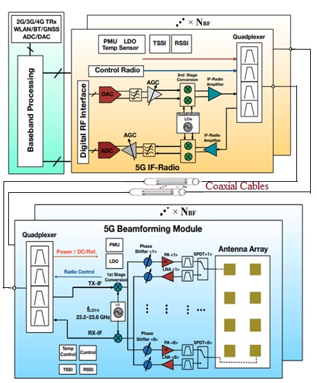
In order to support massive MIMO/beamforming multiple PAs, LNAs, phase shifters, RF filters and SPDT switches are incorporated in the 5G cell phone design. The 5G phone is backward compatible to 2G/3G/4G, WLAN, Bluetooth, GNSS etc. The 5G phone shown is based on heterodyne architecture and advantages of Heterodye receiver.
Radio Frequency Front End (RFFE) control signals are used to carry TSSI and RSSI informations. TSSIstands for transmitter signal strength indicator and RSSI stands for receiver signal strength indicator. As a result, the temperature control of the beamforming module and its calibration are performed.
PMUs (Power Management Units) and LDOs (low drop-out regulators) are used in beamforming part of the 5G cell phone. They transform DC voltage of coaxial cable to different power supplies for use in various dies for cell phone operation.
Note: The figure has been taken from the paper on "5G Cellular User Equipment: From Theory to Practical Hardware Design" which is published on July 18,2017 at IEEE Access by YIMING HUO1, XIAODAI DONG1 and WEI XU2.
5G Technology Features, bands, architecture, deployment, 5G Mobile phones
This 5G wireless technology section covers 5G features, 5G bands, 5G architecture, 5G deployment modes, 5G mobile phones manufacturers, 5G cell phone architecture etc. in the form of tutorials, terminologies and articles.
Introduction:
5G wireless technology is similar to other cellular wireless technologies such as 2G, 3G and 4G. It supports same as well as advanced features compare to backward wireless technologies. Refer 4G vs 5G >> for difference between 5G and other wireless technologies. It supports various frequency bands across the world including above 6 GHz (mmwave bands), below 6 GHz and below 1 GHz. Refer 5G NR Bands >> or 5G Frequency Bands >>. The 5G throughputs of about 20Gbps in the downlink and 10Gbps in uplink are benchmarked by most of the 5G network operators. Throughput speeds of about 5Gbps to 10 Gbps have been achieved during 5G field trials by them till now.
5G wireless technology is similar to other cellular wireless technologies such as 2G, 3G and 4G. It supports same as well as advanced features compare to backward wireless technologies. Refer 4G vs 5G >> for difference between 5G and other wireless technologies. It supports various frequency bands across the world including above 6 GHz (mmwave bands), below 6 GHz and below 1 GHz. Refer 5G NR Bands >> or 5G Frequency Bands >>. The 5G throughputs of about 20Gbps in the downlink and 10Gbps in uplink are benchmarked by most of the 5G network operators. Throughput speeds of about 5Gbps to 10 Gbps have been achieved during 5G field trials by them till now.
5G NR (New Radio) architecture

5G NR overall architecture is shown in the following figure-2. This is as defined in the 3GPP TS 38.300 specification. Refer 5G network architecture >>
5G Deployment Scenarios or modes

There are two modes underwhich 5G Cell phone operates viz. standalone and non-standalone. In non-standalone mode, 5G cell phone relies on backward technology such as LTE for control channel signaling and performs data handshake in 5G wireless mode. In standalone mode, 5G cell phone performs both control and data handshake itself without the need of any backward standards or technologies. Refer 5G Deployment Modes>> for more information.
5G NR Network Interfaces

Refer 5G NR network interfaces which include Xn interface, NG interface, E1 interface, F1 interface and F2 interface. Refer 5G NR interfaces >>.
5G NR Frame Structure


This page describes 5G NR Frame structure. It describes 5G frame as per NR (New Radio) 3GPP standard. The 5G NR frame structure depicts subframes,slot and symbol configurations. Refer 5G NR Frame Structure >>.
5G Channel Types

5G channel types cover logical channels and transport channels used in uplink and downlink with mapping between them. The 5G logical channels include xBCCH, xCCCH, xDCCH, xDTCH etc. The 5G transport channels include xBCH, xDL-SCH, xRACH, xUL-SCH etc. Refer 5G Channel Types >>.
5G Protocol Stack

The 5G layer-1 is PHYSICAL Layer. The 5G layer-2 include MAC, RLC and PDCP.The 5G layer-3 is RRC layer as shown in 5G protocol stack. Refer 5G protocol layer functions >>.
5G NR Physical layer processing for PDSCH and PUSCH

This article describes 5G NR physical layer. The physical layer processing for 5G NR PDSCH channel and 5G NR PUSCH channel have been covered stepwise. This 5G physical layer description is as per 3GPP physical layer specifications. Refer 5G NR PHY >>.
5G NR MAC Layer Overview

This page describes overview of 5G NR MAC layer. It covers 5G NR MAC functions, 5G NR MAC architecture, 5G NR MAC channel mapping, 5G NR MAC procedures and format of 5G NR MAC header and subheaders. Refer 5G NR MAC Layer >>.
5G NR RLC Layer Overview
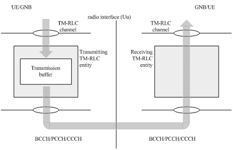
This page describes overview of 5G NR RLC layer including functions. It covers 5G NR RLC modes (TM mode,UM mode, AM mode),data structures (TMD, UMD, AMD),RLC PDUs (TMD PDU, UMD PDU, AMD PDU), data transfers (TM, UM and AM) and RRC parameters which defines RLC layer. Refer 5G NR RLC Layer >>.
5G NR PDCP Layer Overview

This page describes overview of 5G NR PDCP layer including functions. It covers PDCP architecture (structure, entities), PDCP procedures for data transfer during transmit/receive operation, Data PDU and Control PDU formats of PDCP layer etc. Refer 5G NR PDCP Layer >>.
5G NR Initial Access Procedure

5G NR Beam Management Operations

5G NR Uplink Power Control
In wireless systems it is often required to either increase or decrease the transmit power of UE or mobile device. This is known as uplink power control.
Refer 5G NR Power Control Procedure >>.
Refer 5G NR Power Control Procedure >>.
5G NR Uplink Timing Control
In wireless cellular systems it is required to adjust timing of the uplink frame in order to have alignment with downlink frame in time scale. As we know uplink frame is transmitted by UE towards gNB where as downlink frame is transmitted by gNB towards UE. gNB is the 5G NR base station. The timing control procedure is initiated by MAC layer and conveyed to the PHY layer for time adjustment.
Refer 5G NR Timing Control Procedure >>.
Refer 5G NR Timing Control Procedure >>.
5G Cell phone architecture | 5G Mobile Phones Manufacturers
Refer 5G cell phone architecture >> article which describes block diagram of 5G cell phone including its basic components and their respective features.


The term WiMAX stands for Worldwide Interoperability for Microwave Access.
16d fixed
16e mobile wimax
WiMAX has greater coverage diatance than WiFi or WLAN. WiFi cover range of about 30 m, while WiMAX cover radius of about 50 km. WiMAX should be able to support data rate of about 70Mbps theoretically with higher modulation scheme such as QAM.

16d fixed
16e mobile wimax
WiMAX has greater coverage diatance than WiFi or WLAN. WiFi cover range of about 30 m, while WiMAX cover radius of about 50 km. WiMAX should be able to support data rate of about 70Mbps theoretically with higher modulation scheme such as QAM.

Subscribe to:
Posts (Atom)